A relentless increase in data rates is turning the PCB connector landscape upside down. And the clean transmission of signals via PCB traces is becoming more critical while data speeds in servers, switches, routers, and storage devices hit the roof.

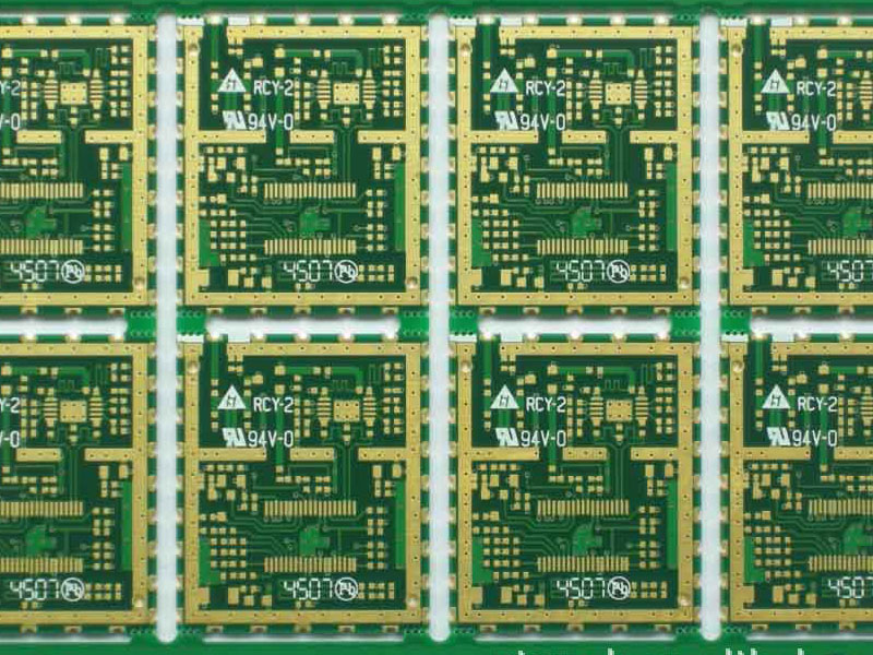
Image: TE Connectivity.
So how do we enhance I/O connections on the board? Here are a few connector-related design parameters that matter a lot in the creation of efficient PCB designs:
Form factor
First and foremost, a small connector footprint simplifies the PCB design, lowers the cost, and reduces the transmission losses while making the connection from point A to point B. Here, a small contact pitch makes the connector slimmer and, thus, facilitates smaller boards and backplanes.
For instance, connector receptacles can be mounted in parallel with a smaller pitch distance, and subsequently, the small receptacle footprint facilitates the connector size reduction. The smaller width of the receptacle is especially useful when multiple connectors are positioned on a single PCB side by side.
Signal losses
The insertion losses are becoming critical with an exponential rise in data rates. So how to overcome the insertion losses? The internal structure, as well as contacts inside the connector, play an important role in improving signal integrity and minimizing insertion losses.
The connector can also enhance the signal interface by improving the airflow and channel impedance.

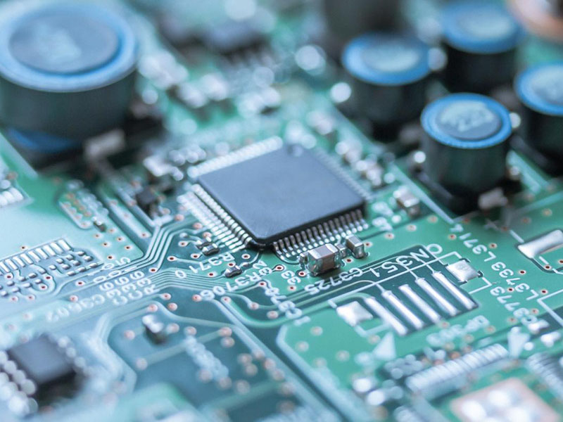
Image: Samtec.
EMI and ESD shielding
The shield against electromagnetic interference (EMI) and electrostatic discharge (ESD) is becoming more crucial at higher data rates. Here, physical envelopes, as well as special mounting and termination mechanisms, play a significant role in ensuring protection against the EMI and ESD effects.
Cable termination
It’s the transitioning point at which the cable is terminated with the connector, and it’s instrumental in overcoming signal losses. For example, some PCB connectors come with pre-loaded springs to prevent unintended cable removal.
And then there are connectors that integrate the wire-termination unit and cable clamp into a single plug shell.
Mechanical strength
A flexible, robust, and durable connector design means that it can withstand cable pull, heat, shock, vibration, and other external forces. The PCB connector’s mechanical strength also ensures proper mating and connection security.
The connector manufacturers facilitate this vital requirement with signal contacts that are pre-loaded, positioned, and protected in individual slots to ensure appropriate connector alignment and mating. The connector suppliers are also using active latches, weld tabs, and board locks to ensure complete and secure mating.
FAQs:
1) What are the electrical requirements for connectors?
A great place to start narrowing options is with the electrical requirements. How many signals do you have in total? What voltages, frequencies and currents are they carrying? This is a multi-dimensional list. Your signals could be digital, analog, power, or even a combination of all three. Also note that digital and analog signals may be either low frequency or high frequency.
The precise combination of signals will usually affect the pinout, connector type and wiring harness. Here are some examples:
• High frequency signals may couple into adjacent wires in a harness, or they may need coaxial connection
• Low-level analog signals could require shielding
• High voltage pins may have clearance and creepage distances to take into account, or they might mandate the use of high dielectric strength materials
• High current paths may call for larger wires or multiple pins
Be aware that some combinations of signals may not be suitable for inclusion in the same connector. Are you dealing with only electrical signals, or are there some fiber-optic connections to be added? Some applications such as surgical equipment also require liquid or gas lines. If this is the case and if your design requires everything to be on the same connector, you’ll probably have to go with a custom solution.
2) Are there size or space constraints? Miniature Connectors
As you know, the past few decades have shown a continuing trend towards size reductions in just about all categories of electronic equipment. Computers have gone from under-desk towers to laptops to tablets to single board computers and wearables. Many items that used to be permanently situated in a room – X-ray machines, for example – are now on wheels. This has led to a corresponding reduction in the size and weight of connectors and the space available for them, while their need to be able to withstand an increased frequency of mating and unmating has increased.
If this situation applies to your current project and you are looking for some connector options, we have over 32,000 D-subminiature connectors of all types to help match your design needs.
3) Will the connector be operating in an extreme environment? Backshell Connectors
Many connector systems are subject to extreme mechanical conditions such as shock or vibration. A connector designed for such conditions often incorporates special features such as a threaded coupling that cannot vibrate loose or a strain relief (like a backshell) to support the wiring harness. You will typically find ratings for shock and vibration resistance in the specifications as well as highlighted at the top of the datasheet if the product has been specially designed to withstand extreme conditions.
Another common environmental concern is extreme temperature. Will your connector be located outdoors or indoors but near a frequently opening external door? Is there a heat source near where you are mounting the connector? Special materials and insulators are used to protect the connector and contacts, ensuring it can be reliably and repeatedly mated and unmated. Pay attention to the recommended operating temperature range in the data sheet.
4) Is sealing needed to protect against water, oil or gas? The Ingress Protection Rating
Certain environments demand protection against intrusion from liquids or dust of varying degrees. Environmental sealing options start with a simple protective boot and boot adapter, useful against occasional splashes. The next level of protection involves sealing the connectors themselves. If your application requires environmental sealing, the IP code system rates connectors by the degree of protection provided against dust and water intrusion. Once you know the level of protection required, you can check the IP rating number in the specifications to determine if you have a viable solution.
There are many industries that require more than just protection against occasional accidental liquid exposure. Medical and food applications must withstand common sterilization procedures that involve high temperature and high pressure water, while under-hood automotive applications must be proofed against steam cleaning or road hazards such as water, solvents or salt spray. The most stringent environments (space, underwater or aerospace) may call for hermetic sealing, which tests a connector based on leakage of gas through the system.
You should also find out whether your environment requires electronic components that are rated for a Class 1, Division 2 hazardous location that poses a risk of flammable or combustible gases, liquids, vapors or debris. Electrical equipment installed in such a location should be designed and tested to ensure it won’t initiate an explosion. Products certified for this type of hazardous location have a mention in their specifications for a Class 1, Division 2 intrinsically safe rating.
5) Are there any mandatory industry standards to meet?
Many industries impose their own standards that OEMs must meet. Even if these standards don’t cover connectors specifically, they apply to the equipment that the connector system is part of. The FDA sets standards for medical equipment, while automotive applications adhere to SAE standards, especially for high-voltage use in electric and hybrid vehicles. And let’s not forget the multiple sets of MIL standards pertaining to defense-related equipment. These standards often cover not only performance and reliability, but also stringent qualification and manufacturing standards. Check to confirm the necessary standards you must follow within your industry.
6) What level of reliability is needed? Connector Mating Cycles
Another critical item to consider is the projected standard use case. How often will the connector be mated and unmated? Scenarios range from one-time use to 10,000 or more cycles.
Sometimes both will coexist in the same system – a patient sensor wiring harness may come pre-assembled from the manufacturer with a connector intended for one-time use, whereas its mating receptacle on the diagnostic equipment may be rated for thousands of cycles. In an automotive application on the other hand, the connectors may stay mated together for the life of the vehicle.
Some connectors list a specification for MTBF (Mean Time Before Failure) or MTTF (Mean Time To Failure) with calculated estimates for the life of the product under “standard” use. This can serve as a guide for whether the connector is right for your application. If the connector’s cable will be located on a door or perhaps on a robotic arm that requires daily bending of the cable, it is recommended that you check the maximum bend radius spec of the cable and whether or not it works with a “high flex” cable option.
Connector reliability is a complex subject – it depends on multiple factors, and precise figures are usually difficult to determine.
7) What kinds of terminations are required?
Terminations are used to join the connector pin or socket to its associated conductor – whether it’s a wire, PCB trace or something else. There are several different terminal types available, including crimped connections, soldered connections, press-fit (in a ribbon connector, for example) or even wire-wrap. Each one naturally comes with its own advantages and disadvantages. For example, crimped connections are easier to repair in the field. Termination selection typically depends on your design and application as a whole.